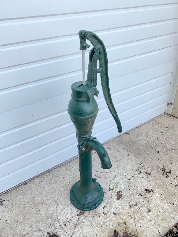
When I was a kid my grandpa used to take my sisters and me to a certain park in the Chicago Park District to perform a ritual on Sundays after church. We didn’t go there to play on the swings, or throw a ball for a dog; we went there to fill up glass jugs with water at a well with a hand pump. Clack-clack, clack-clack, gusssh. Grandpa was a big believer in the healthful properties of freshwater, pumped from a well.
Forty years later I bought a rural property with its own well, and of course one of the first things I wanted was a hand pump put on the well. I bought the hand pump, but immediately ran into problems with the installation: hand pumps aren’t made to share space with an existing household electric pump down in the well casing.
The problem is that both pumps expect to sit in the middle of the well casing when you use standard mounting parts. What is needed is a way to offset each pump assembly from the other. I found that I could move the electric pump off to one side using something called a pitless adapter, but I could not find an off-the-shelf commercial solution for offsetting the hand pump.
I decided to design a custom hand pump mounting platform that would clamp onto the well casing while providing the necessary offset, using an open source software program called FreeCAD from freecadweb.org/…. My employer graciously consented to cut the steel parts using their half-million-dollar water jet cutting machine, so I was off and running. This is a review of my experience using FreeCAD to design a multiple-part assembly in 3-D.
FreeCAD has enormous capabilities serving various fields of engineering like architecture, optical design, robotics, and more, but 99% of the public is going to be interested in its mechanical part design capabilities, as I was. I won’t be able to give you a detailed tutorial in this brief review, but I want to convey something about the flavor of what it is like to work with FreeCAD.
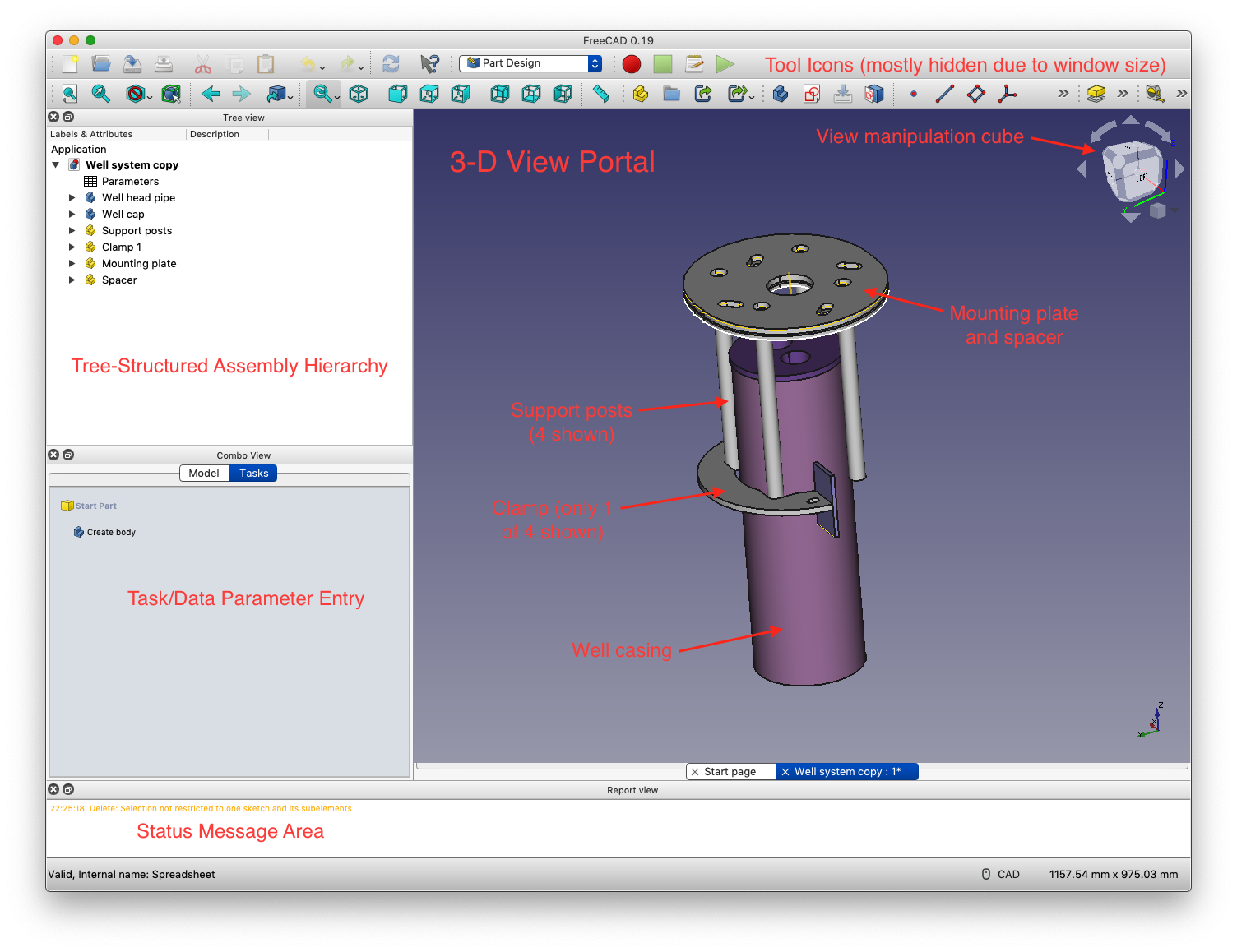
When you start the program you’re presented with a main window, and three auxiliary panes. At the top is the pane containing tool icons, on the left is a pane that is shared by parameter inputs and a structured tree view of your assembly, and at the bottom is a status window pane. The main window is where you view your assembly in 3D, and it is also where you create sketches, which are 2D drawings.
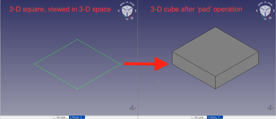
FreeCAD works similarly to other CAD programs when it comes to designing a three-dimensional part: you start by creating a two-dimensional sketch and then perform some operation on the sketch to make it three-dimensional. A very common operation that you will use often is the ‘pad’ or ‘extrude’ tool: this operation takes a closed line 2-D figure, like a square, and extrudes it outward in the third dimension, creating a box or a cube.
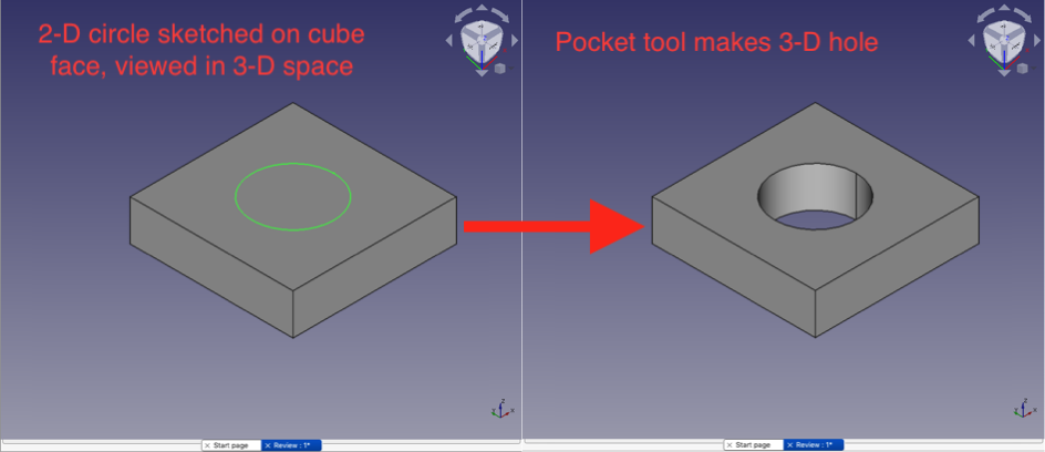
Once you have a three-dimensional object like a box you can create another sketch, and use that 2-D figure to create a ‘pocket’ or hole operation through the original 3-D object.
With just the pad and pocket tools, you can create an amazing number of objects, but of course, FreeCAD has some other 2-D to 3-D transformations that you can utilize as well: you can do a revolved extrusion, or even a helical extrusion, a sweep along a path, or a loft through two different profiles as additive actions. There are also subtractive equivalents that create simple grooves and helical grooves, subtractive sweeps, and lofts, etc.
Finally, once you have a 3-D object you can replicate it linearly or in polar fashion, you can perform three-dimensional Boolean operations, etc. If you’re interested in FreeCAD for the purpose of making simple three-dimensional parts using a 3D printer then this is probably as far as you need to go to master FreeCAD.
I want to talk about the sketching process in more detail before I tell you about one of FreeCAD’s killer features. Central to the idea of creating a sketch is the concept of constraints. FreeCAD has a large range of constraints that you can apply to elements in a 2D sketch: you can define the length of a line or the angle of a line. You can define the radius or diameter of an arc or circle. You can constrain one end of a line to be coincident with the end of another line, or tangent to the circle. You can thus see that constraints are really just a generalization of the dimensions that you might be familiar with seeing on an old-fashioned factory part drawing.
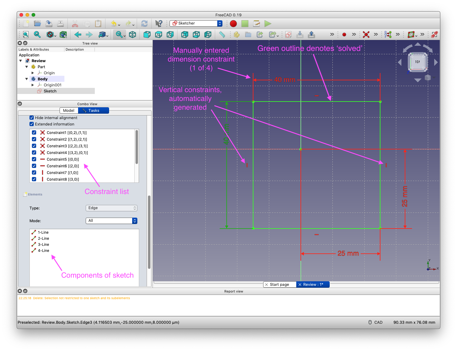
The sketching environment is pretty smart about supplying constraints automatically: if you start a line by clicking within a certain small distance from another feature, the end of another line, for instance, it will assume that you intended to make that start of the new line coincident with the endpoint of the old line. Similarly, if you draw a line that is pretty close to horizontal in angle it assumes you want a perfectly horizontal line, and it will generate a “keep this line horizontal” constraint for you.
These little automatic constraints are usually very helpful in making your workflow more efficient, but there is a list of the currently active constraints in the left panel where you can delete anything that isn’t intended – sometimes you really do want a line that is a shade off from horizontal.
Suppose you are in the sketching workbench environment, called Sketcher, and you want to create a square. You can click on the rectangle tool icon, then click once for one corner of the square, and click again to define the other corner. That simple two-click operation actually results in four lines that come in with a bunch of assumed constraints: the ends of the lines are connected and the horizontal lines are truly horizontal and the vertical lines are truly vertical.
And although you clicked intentionally to make the square a certain size and in a certain position, FreeCAD wants you to formally define the X and Y sides with dimensions and define the position with offsets in X and Y from the origin; those are constraints that you can apply manually from the constraint palette of tool icons, and they require you to type in a number for each distance. When your sketch is completely formally defined, the Sketcher environment will tell you that it is ‘solved,’ and the figure will be outlined in green.
FreeCAD’s killer feature is related to constraints, and it is called parametric modeling. Parametric modeling allows you to replace hard-coded constants in constraints with values that are stored in a table and referred to by a meaningful name that you assign. You can even define a constraint or position to use a formula that contains table values. This is incredibly powerful because it allows you to change your design without having to go in and hand-modify all of the sketches individually where a particular dimension might have been used.
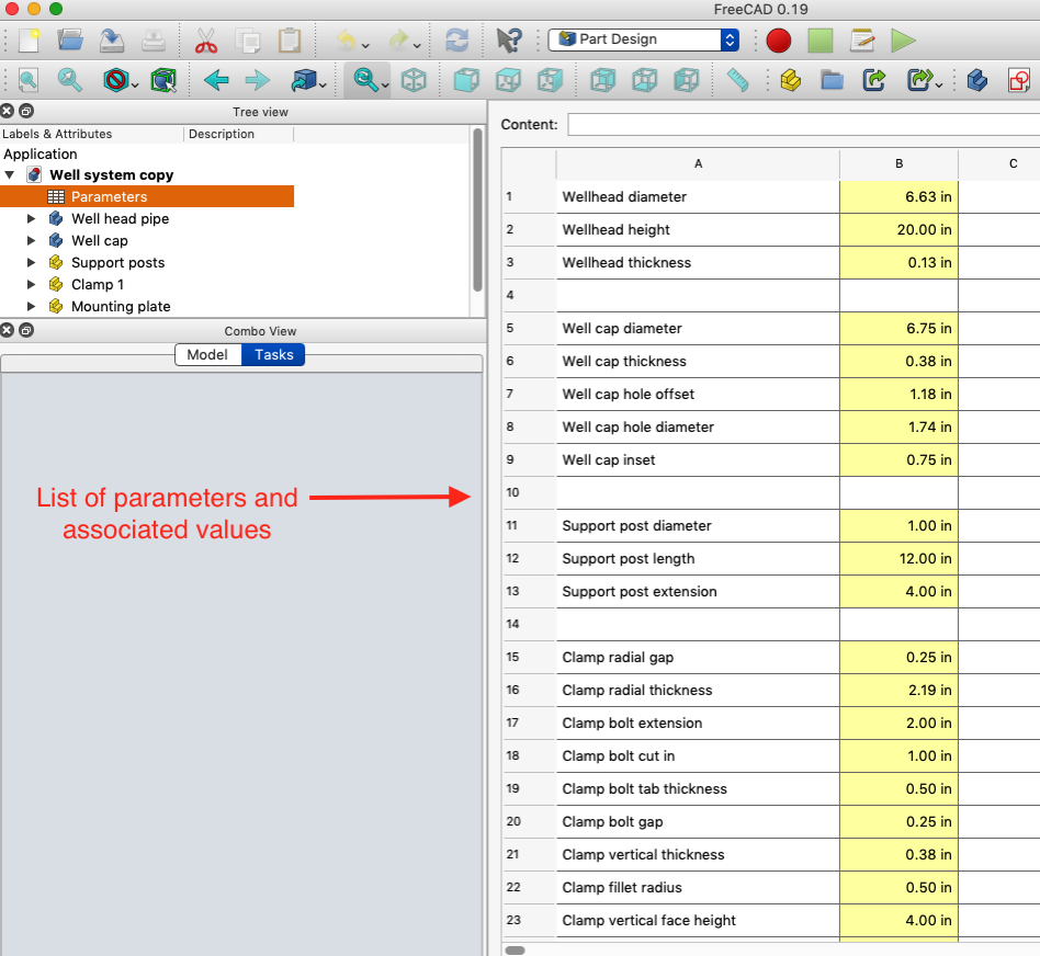
To give you an idea of how powerful parametric modeling is, I defined nearly everything in my well support system parametrically. At a certain point, I decided that the three-quarter-inch support posts looked too flimsy, so I changed the entry for the support post diameter in the spreadsheet to one inch. Every other part in the design scaled automatically to accommodate the change! It was freakin’ magic.
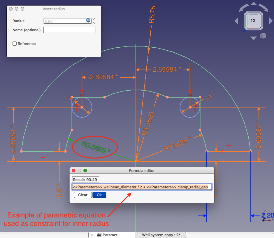
The sketching environment also allows you to create construction lines and arcs that you can then use to form the basis for other constraints on real object geometry; I used this feature to play around with where the slots would fall in the mounting plate – I made the angle of a construction line that defined the start of one slot to be a parametric variable, and then I was able to change the value in the spreadsheet to find an angle where the slots didn’t interfere with the support posts.
This is a review, so I want to talk about how well all of this works. I found Sketcher easy to use and really quite intuitive. For collections of simple lines and arcs that don’t need to be referenced to other parts, it is efficient and darn near bulletproof.
One limitation of FreeCAD currently is that when you’re creating a sketch you don’t automatically have access to create a constraint off an edge or point that exists on another part of the assembly. You can see the edge or point (unless you’ve turned it off in the tree view), but you can’t click on it as part of a constraining operation. It has to be imported into the body that contains the sketch and made explicitly available using a tool called the Shapebinder; you can think of the Shapebinder as a container that holds information about the edges and points from other parts that you want to use in this part. I think you’ll find that commercial software like Solidworks allows you to seamlessly reference edges on other parts while sketching, a huge advantage.
Another problem that is easy to run into is over-constraining your sketch. For instance, if you have a situation like I did, where I wanted to have slots on two different parts line up with each other, you have to be really careful when sketching out the second slot – I found it best to purposefully draw the second slot well enough away from the imported features of the first slot so that the automatic constraints didn’t kick in, and then manually add constraints to bring the second slot into alignment. It can be easy to back yourself into a corner where you have a long list of constraints, mostly automatically generated, and you don’t quite know which ones to get rid of to fix an over-constrained sketch.
As you can see in the screenshot earlier of my well pump mounting system, I created a number of different components and placed them in relation to each other in 3-D space (although, I only show one of the four clamps). I used parametric equations to define how all the parts should be positioned relative to each other, which meant that if I wanted to create more space between the top of the well cap and the mounting plate all I had to do was change an entry in the spreadsheet.
However, setting it up was a bit tedious, though that was an effort that occurred incrementally as the design progressed. This is another area where commercial software is better; in Solidworks you can grab a part with the mouse, rotate it as you do in Tetris, and then mate it to another face or edge as needed. The FreeCAD developers have been actively working on the Assembly workbench, and likely this situation will improve in the next release.
One little annoyance of FreeCAD is that it doesn’t completely support arbitrary units of measurement – it really wants you to use millimeters. You can set it to use inches, and it will respect hard-coded dimensions that you make in inches, but anything you put in the spreadsheet has to be millimeters – though it will display it back to you in inches!
One aspect of the program that I found confusing was the differences between parts and bodies in the tree hierarchy. Hierarchically, bodies sit below parts, so apparently, multiple bodies can form one part as I did with the clamp. You must export parts when creating IGES or DXF files, it appears.
You might be wondering, do I need a powerful computer to run FreeCAD? I would say no, based on the fact that I created this entire design using a 2017 dual-core MacBook Air with built-in Intel graphics hardware, not exactly a powerhouse computer. I was even able to work with it on the built-in screen, though I was much more comfortable and effective when I hooked up an external monitor (which was still only 1920 by 1280). The program uses about 100% of one CPU core, especially when the full assembly is being viewed, so the fan was definitely running most of the time.
The final question that I want to address is, how attainable is FreeCAD mastery to ordinary mortals? I would say that yes, someone without CAD experience can master most of FreeCAD in something like a week of evening study. I have to confess that this was actually my second attempt to learn FreeCAD; I took a run at it a couple of years ago but found that the learning resources were meager at that time, and the program itself was, of course, not as well-developed.
This time around I managed to find a couple of really good tutorials on YouTube channels; I watched the videos and took notes, and then tried to replicate the tutorials on my own. Inevitably, I would find that I had missed a step, so I would go back to the video and watch that section again. Repeat until mastery arrives.
The FreeCAD documentation wiki is very complete and accurate, but generally speaking, you have to know what you’re looking for in order to be able to use it. FreeCAD appears to have a sizable user and developer community, so you can get assistance in the forum if you need help.
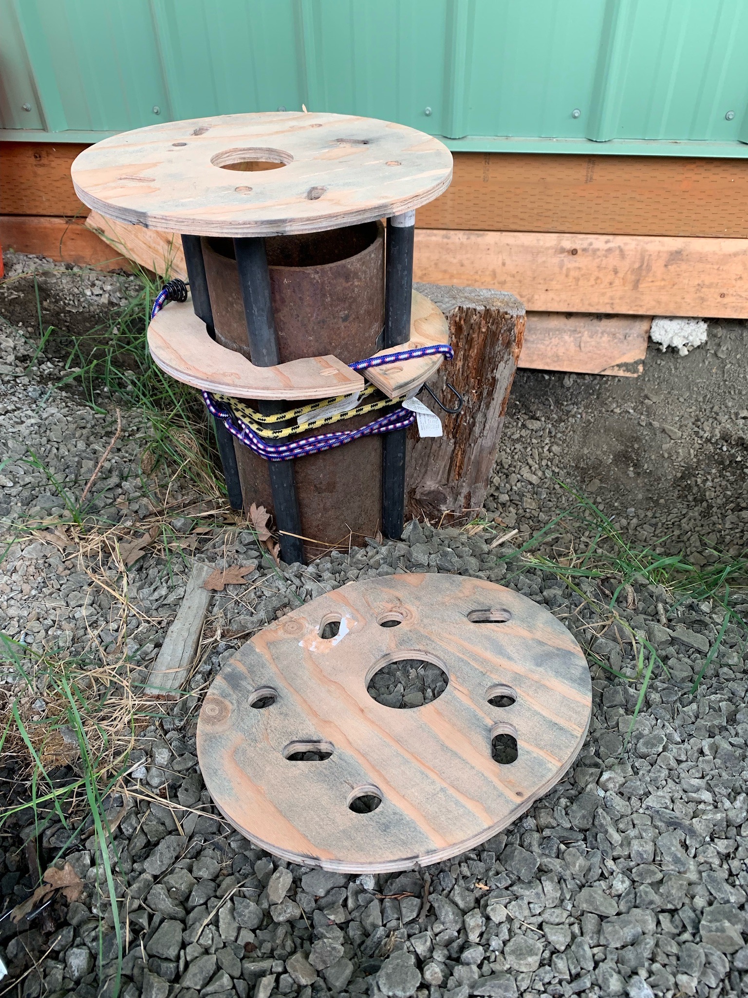
All in all, I was very happy with FreeCAD and my design project was successful (although not yet quite complete – the plywood prototype parts have been cut and fit well on the well casing, but I haven’t yet committed to cutting steel). If you want to get involved in the maker community, or just want to document a woodworking project, I wouldn’t hesitate to reach for FreeCAD. As you might guess, the price to performance ratio is very favorable!
Links:
- FreeCAD web site: https://www.freecadweb.org/
- FreeCAD wiki: https://wiki.freecad.org/Getting_started
- Basic YouTube tutorial series: youtube.com/… (I really liked this presenter’s videos; they start from the basics and get pretty advanced, all the while emphasizing best practices)
- Simple example part using pad and pocket tools: youtube.com/… (presenter also has some other videos worth watching)
- Shapebinder tutorial: youtube.com/…
- Managing multi-part models: youtube.com/… (this video is great for seeing how everything comes together)

